
What Is the Maximum Frequency Rating of a 90 Degree D-Sub Coaxial Contact Terminal
2026-06-15
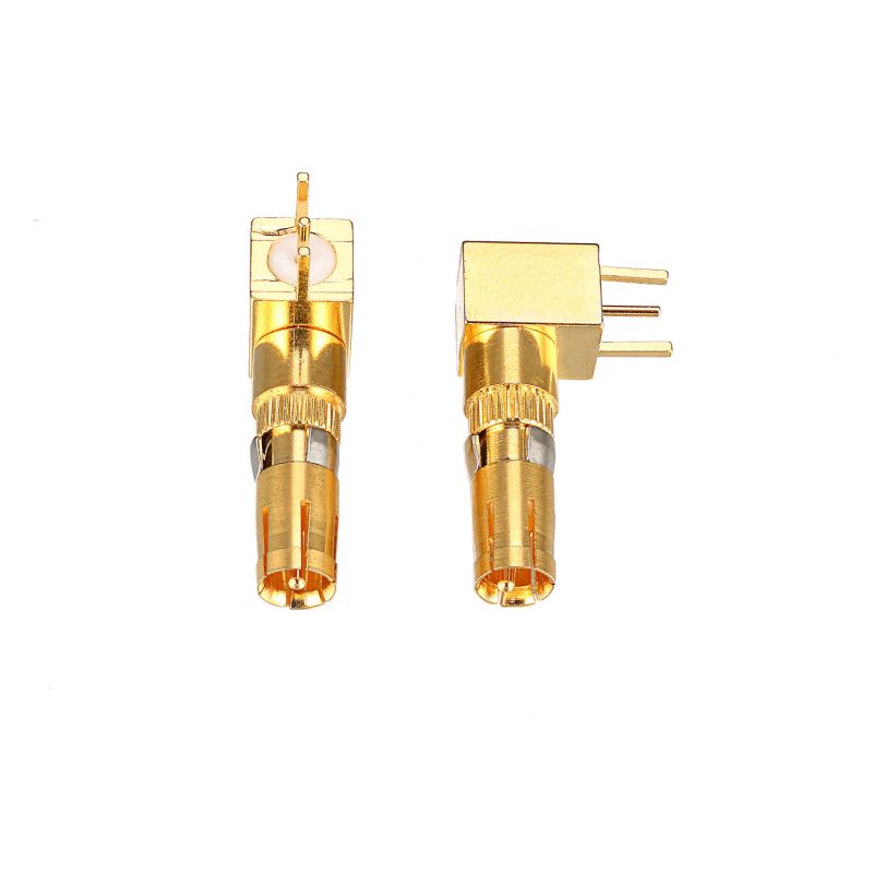
When designing high-frequency systems, engineers often face a critical question: what is the true upper-frequency limit of a 90 Degree D-Sub Coaxial Contact Terminal? At SIGNALORIGIN, we have tested numerous configurations and found that the maximum frequency rating typically falls between 1 GHz and 3 GHz, depending on materials, impedance matching, and assembly precision. This makes the 90 Degree D-Sub Coaxial Contact Terminal ideal for broadcast video, telecom, and test equipment where board space is constrained.
Key Factors Determining Frequency Limits
Several variables directly impact the upper frequency of a 90 Degree D-Sub Coaxial Contact Terminal. The table below summarizes the most critical parameters.
| Parameter | Typical Range | Impact on Frequency |
|---|---|---|
| Impedance (nominal) | 50 Ω or 75 Ω | Mismatch causes reflections above 2 GHz |
| Dielectric material | PTFE (εr ≈ 2.1) or LCP | Higher loss materials reduce bandwidth |
| Contact plating | Gold (30 µin min) | Oxidized surfaces degrade return loss |
| Right-angle bend radius | ≤ 3 mm centerline | Sharp bends introduce capacitance |
| Shielding continuity | 360° closed entry | Gaps cause resonance peaks |
SIGNALORIGIN manufactures each 90 Degree D-Sub Coaxial Contact Terminal with precision-machined bodies to maintain 50 Ω characteristic impedance up to 2.5 GHz, with extended performance models reaching 3 GHz.
Why Right-Angle Design Affects Bandwidth
A straight coaxial contact can exceed 6 GHz. However, the 90° bend in a 90 Degree D-Sub Coaxial Contact Terminal creates an impedance discontinuity. This bend acts as a low-pass filter. Above 1.5 GHz, even minor geometry variations cause voltage standing wave ratio (VSWR) degradation. SIGNALORIGIN solves this by using a patented stepped center pin and oversized dielectric bead around the bend, keeping VSWR below 1.3:1 up to 2.5 GHz.
90 Degree D-Sub Coaxial Contact Terminal FAQ
Q1: What happens if I use a standard 90 Degree D-Sub Coaxial Contact Terminal above its rated frequency?
A1: Operating a 90 Degree D-Sub Coaxial Contact Terminal beyond its maximum frequency (e.g., 4 GHz on a 2.5 GHz rated part) causes three predictable issues: insertion loss increases by 3–6 dB per octave, return loss drops below 10 dB (meaning 10% of power reflects), and radiated emissions spike. In high-density D-sub housings, crosstalk between adjacent coaxial contacts also rises sharply. For applications above 3 GHz, SIGNALORIGIN recommends switching to a shielded right-angle PCB launch or a straight coaxial contact with a flexible jumper.
Q2: Does the mating cycle count affect the frequency rating of a 90 Degree D-Sub Coaxial Contact Terminal?
A2: Yes, significantly. A brand-new 90 Degree D-Sub Coaxial Contact Terminal may perform at 2.8 GHz, but after 500 mating cycles (typical for test equipment), the frequency limit often drops to 1.5 GHz or lower. The root cause is wear on the gold plating at the mating interface, which increases contact resistance and introduces impedance bumps. SIGNALORIGIN uses 50 µin gold over nickel underplate, guaranteeing frequency stability within 5% of initial rating for 1,000 cycles. For high-cycle applications, inspect the contact’s retention spring every 250 cycles.
Q3: Can I mix 50 Ω and 75 Ω versions of the same 90 Degree D-Sub Coaxial Contact Terminal in one connector shell?
A3: Technically yes, but with a major caution. A 90 Degree D-Sub Coaxial Contact Terminal designed for 75 Ω (common for SDI video) has a different center pin diameter and dielectric thickness than a 50 Ω version. Mixing them in the same D-sub shell does not damage the contacts, but the impedance discontinuity at each mixed interface reduces the system bandwidth to approximately 1 GHz, regardless of individual ratings. SIGNALORIGIN provides color-coded insulators (blue for 50 Ω, white for 75 Ω) and recommends using one impedance type per connector shell. If mixing is unavoidable, keep the application below 800 MHz.
Best Practices for Maximizing Bandwidth
-
Use controlled impedance PCBs with 50 Ω microstrip traces matched to the 90 Degree D-Sub Coaxial Contact Terminal.
-
Keep the terminal’s soldered center pin lead as short as possible (< 2 mm).
-
Ground all four surrounding D-sub signal pins to reduce noise coupling.
-
Always torque the jack screw to 0.35 N·m – over-tightening warps the shell and misaligns the contact.
Why SIGNALORIGIN Leads in High-Frequency D-Sub Solutions
Every 90 Degree D-Sub Coaxial Contact Terminal from SIGNALORIGIN is 100% swept-frequency tested from 10 MHz to 3 GHz. We provide individual VSWR and insertion loss plots. Our engineering team has helped over 400 customers deploy right-angle coax contacts in 5G infrastructure, medical imaging, and aerospace telemetry systems.
Contact Us
Have a specific frequency requirement beyond 3 GHz? Need a custom dielectric material for your 90 Degree D-Sub Coaxial Contact Terminal? Contact SIGNALORIGIN today – our RF application engineers will review your stack-up, simulate the bend region, and deliver verified test data within 48 hours. Reach us at [email protected] or through the contact form on our website.