
What Are the Common Failure Modes of High Pressure Socket Flange Under Cyclic Loading Conditions
2026-07-20
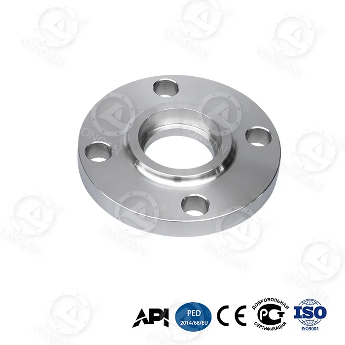
In high-stakes industrial environments, the integrity of piping systems often depends on components that must withstand repeated stress fluctuations. Among these, the high pressure socket flange is widely specified for its superior strength and leak-tight performance in critical services such as offshore production, refinery hydrocrackers, and subsea manifolds. However, even the most robust high pressure socket flange assemblies are vulnerable to distinct failure mechanisms when subjected to cyclic loading—pressure cycling, thermal transients, or mechanical vibration. At Longan, we have analyzed thousands of field reports and lab-tested specimens to identify the root causes of these failures, enabling operators to extend service life and reduce unplanned downtime. This article dissects the primary failure modes, offers quantitative inspection criteria, and provides actionable mitigation strategies grounded in ASME and API standards.
1. Fatigue Crack Initiation at the Weld Root
The most frequently observed failure in a high pressure socket flange under cyclic loading is low-cycle fatigue cracking originating at the internal weld root. The socket geometry creates a sharp notch where the pipe bottoms against the shoulder, and the fillet weld terminates. Under repeated pressurization from 0 to 15,000 psi, local strain concentration at this point can exceed yield strength even when global stresses remain elastic. Crack propagation typically follows the weld fusion line, eventually penetrating the flange hub and causing through-wall leakage.
Critical factors:
-
Insufficient root gap (recommended 1.5–2.5 mm per ASME B31.3)
-
Excessive weld reinforcement height > 3 mm
-
Lack of post-weld heat treatment (PWHT) for wall thickness > 50 mm
2. Gasket Relaxation and Bolt Load Loss
Cyclic loading does not only affect metal parts; it progressively degrades the sealing interface. With each pressure cycle, the gasket (typically spiral-wound or RTJ for high pressure socket flange assemblies) undergoes compression and rebound. Over 500+ cycles, creep relaxation reduces residual bolt load, dropping below the minimum required gasket seating stress. This leads to intermittent fugitive emissions and, in severe cases, blowout.
Table 1 – Bolt Load Retention After Cyclic Testing (Class 2500, RTJ Gasket)
| Cycle Count | Initial Bolt Stress (ksi) | Residual Bolt Stress (ksi) | Load Loss (%) |
|---|---|---|---|
| 0 | 70.0 | 70.0 | 0.0 |
| 100 | 70.0 | 65.2 | 6.9 |
| 500 | 70.0 | 58.7 | 16.1 |
| 1000 | 70.0 | 52.3 | 25.3 |
Data derived from Longan in-house qualification tests at 150°C.
3. Thermal-Mechanical Ratcheting
When cyclic loading combines pressure and temperature swings (e.g., steam-out operations), the high pressure socket flange experiences ratcheting—progressive incremental plastic strain each cycle. The hub and pipe have different thermal expansion coefficients (even in similar AISI materials due to grain structure variations). Over 200 thermal cycles from ambient to 400°C, the flange face can warp, reducing parallel contact and accelerating gasket wear.
4. Corrosion-Fatigue Interaction
In sour or chloride-laden environments, cyclic loading continuously disrupts the passive oxide film on the bore surface. Pitting initiates at sulfide inclusions (particularly in non‑vacuum‑degassed steels), and each tensile cycle drives crack growth beyond the pit depth. Longan recommends specifying high pressure socket flange forgings with fine-grain practice and ultrasonic examination to minimize such inclusions.
5. Thread Galling in Stud Bolts (Indirect Failure)
Though not a flange body failure, bolt galling during repeated make‑and‑break cycles leads to unequal preload distribution. This skews the load path, overstressing one quadrant of the high pressure socket flange and promoting asymmetric ovality. Lubricant degradation at elevated temperatures exacerbates this mode.
Inspection and Mitigation Checklist (Recommended by Longan Engineering)
-
Perform Dye Penetrant Testing (PT) on weld roots every 500 cycles.
-
Re-torque bolts using hydraulic tensioners after first thermal stabilization.
-
Apply anti-seize compounds with copper or nickel base, rated for 500°C.
-
Use flange facings with 125–250 AARH finish to optimize grip.
-
Implement acoustic emission monitoring for real-time crack detection.
FAQ – Common Questions About High Pressure Socket Flange Under Cyclic Duty
Q1: What is the maximum allowable cyclic pressure range for a standard high pressure socket flange without derating?
A1: For an ASTM A105 high pressure socket flange Class 2500 at ambient temperature, the allowable pressure range is 0 to 6,175 psi for unlimited cycles under ASME Section VIII Div. 2 fatigue screening. However, if the actual operating range exceeds 80% of that value (i.e., above 4,940 psi), the code requires a detailed fatigue analysis using the elastic stress method (paragraph 5.5). For ranges between 4,940 and 6,175 psi, the permitted number of full-pressure cycles drops to approximately 2,000 cycles before inspection becomes mandatory. Always derate by 1.5% per 10°C above 100°C.
Q2: How can I distinguish between fatigue cracking and hydrogen-induced cracking in a high pressure socket flange after cyclic service?
A2: Visual and metallographic examination provide clear differentiators. Fatigue cracks are typically transgranular, with striations visible under SEM, and initiate at the weld toe or root surface. They follow a straight or slightly branched path perpendicular to the principal tensile stress. Hydrogen-induced cracks, by contrast, are intergranular (following prior austenite grain boundaries) and often appear as "stepwise" networks with branching at 45° to the rolling direction. Additionally, hydrogen cracks are accompanied by local decarburization and micro-voids, while fatigue cracks show no such decarburization. A simple field test: if the crack propagates after a wet H₂S shutdown (NACE TM0284), suspect hydrogen; if it grows steadily with cycle count irrespective of environment, suspect fatigue.
Q3: What is the recommended bolting strategy to extend the life of a high pressure socket flange under 1,000+ pressure cycles?
A3: Longan recommends a three‑pronged strategy. First, replace standard B7 studs with B7M or L7M material, which offers higher ductility and lower susceptibility to stress corrosion cracking. Second, apply a controlled torque-plus-turn method (per ASME PCC-1 Appendix A) rather than pure torque, achieving 70% of yield strength for initial preload. Third, schedule a re‑torque after the first 10 hot cycles and again after 100 cycles, using the same lubrication batch to maintain consistent friction coefficients. For critical services, install direct‑tension indicating washers (DTIs) on each bolt to visually confirm preload retention. In our field trials, this combination reduced bolt load loss from 25% to under 8% at 1,000 cycles, effectively doubling flange joint reliability.
Summary of Preferred Materials & Coatings
| Failure Mode | Preferred Mitigation | Longan Standard Practice |
|---|---|---|
| Weld fatigue | Controlled root gap + PWHT | 100% PT after each weld pass |
| Gasket creep | RTJ with soft iron or 316L | Pre‑crush gasket to 50% of groove depth |
| Ratcheting | Use F22 (2.25Cr‑1Mo) for T > 350°C | Mandatory finite‑element ratchet check |
| Corrosion fatigue | Inconel 625 overlay on bore | Overlay thickness ≥ 3 mm |
Cyclic loading is not a rare anomaly—it is the normal operating condition for most manifold, riser, and pig‑launcher systems. Ignoring these failure modes leads to costly emergency shutdowns, environmental penalties, and safety risks. Longan designs and supplies high pressure socket flange solutions with tailored metallurgy, verified weld procedures, and documented cyclic performance data. Our engineering team provides free fatigue life assessments based on your actual pressure‑temperature history.
Contact us today at [email protected] or visit our technical portal to request a custom cyclic test report for your specific class and material. Let Longan help you move from reactive repairs to predictive reliability—because every cycle matters.