
Article Summary
Choosing a flange is about much more than matching a nominal diameter. Engineers and purchasing teams must consider dimensional standards, pressure and temperature conditions, material specifications, gasket compatibility, welding requirements, and long-term maintenance. The DIN2632 PN10 RF Weld Neck Flange Carbon Steel A105 S235JR combines several important specifications in one product description, but each designation must be interpreted correctly before an order is placed.
This guide explains the meaning of DIN 2632, PN10, RF, weld neck construction, ASTM A105, and S235JR. It also covers dimensional verification, installation, inspection, common procurement mistakes, and practical questions that help buyers specify the right flange for their piping systems.
1. Understanding the Product Specification
In industrial piping, a flange is a critical connection component that allows pipes, valves, pumps, and other equipment to be assembled, inspected, and maintained. However, an incorrect flange specification can create expensive problems, including bolt-hole misalignment, leakage, welding difficulties, delayed installation, and premature component replacement.
The keyword DIN2632 PN10 RF Weld Neck Flange Carbon Steel A105 S235JR describes a flange by combining its dimensional standard, nominal pressure class, facing configuration, connection design, and material requirements. Understanding these elements helps buyers communicate more accurately with manufacturers and avoid misunderstandings during quotation and production.
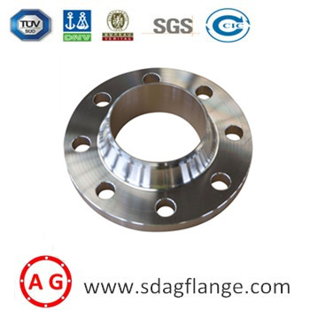
A weld neck flange features a projecting hub that transitions toward the pipe connection. The flange is normally joined to the pipe by a butt weld, following an approved welding procedure. This construction is commonly considered for piping systems where structural continuity, dependable alignment, and resistance to operating loads are important.
Nevertheless, a product name alone does not establish that every component is suitable for every service condition. The actual drawing, material specification, pressure-temperature rating, manufacturing standard, and inspection documents must agree with the project requirements.
2. What Each Designation Means
| Designation | Meaning | What Buyers Should Verify |
|---|---|---|
| DIN 2632 | German standard designation historically associated with PN10 welding neck flanges. | Applicable dimensional edition, nominal size, and project standard. |
| PN10 | Nominal pressure designation of 10 bar. | Allowable working pressure at the actual operating temperature and service conditions. |
| RF | Raised face, a gasket-contact surface projecting above the surrounding flange face. | Facing dimensions, finish, gasket type, and mating-flange compatibility. |
| Weld Neck | Flange construction with a hub designed for butt welding to a pipe. | Pipe outside diameter, wall thickness, bore, and welding preparation. |
| ASTM A105 | A specification for carbon steel forgings used in piping components. | Applicable edition, mechanical properties, heat treatment where required, and material certification. |
| S235JR | A structural steel grade designated under the European steel specification system. | Applicable product standard, delivery condition, impact requirements, and suitability for pressure service. |
DIN 2632 belongs to a historical family of German flange standards. Its dimensions are often compared with corresponding flanges under EN 1092-1, but buyers should verify the specific size, facing, tolerances, and drilling pattern rather than assuming universal interchangeability. See a DIN 2632 PN10 dimensional reference.
3. Why Weld Neck Flanges Matter in Industrial Piping
Flange failures are not always caused by insufficient material strength. Poor alignment, excessive external loads, incorrect welding, damaged gasket faces, and unsuitable bolting can all compromise a joint. Weld neck construction helps address some of these challenges when properly designed and installed.
3.1 A Gradual Hub Transition
The tapered hub provides a gradual transition between the flange body and the pipe. This geometry can help distribute stresses more favorably than some flange configurations, especially when the joint is exposed to changing loads. The actual benefit depends on dimensions, material properties, weld quality, and the complete piping design.
3.2 A Butt-Welded Connection
A correctly prepared and executed butt weld creates a permanent connection between the flange and pipe. The joint can be inspected using appropriate visual, surface, or volumetric examination methods according to the project specification. Welding procedures and personnel qualifications should meet the applicable code and quality requirements.
3.3 Suitability for Engineered Piping Systems
Weld neck flanges are commonly considered for industrial utility lines, water distribution systems, process piping, and equipment connections. They are especially useful when the engineering design values structural continuity and inspectability. They are not automatically superior for every low-pressure application, because cost, installation access, maintenance needs, and operating conditions also matter.
- Reliable alignment: Correct bore and pipe preparation support a consistent connection.
- Inspection access: The butt-weld joint can be examined according to an approved inspection plan.
- Long-term serviceability: A properly engineered joint can support planned operation and maintenance.
- Application flexibility: Material, size, facing, and finish can be specified to match project requirements.
4. A105 and S235JR Material Considerations
Material selection is one of the most important parts of specifying a carbon steel flange. A105 and S235JR are not simply two interchangeable names for the same material. They originate from different specification systems and serve different defined purposes.
4.1 ASTM A105 Carbon Steel Forgings
ASTM A105 covers carbon steel forgings for piping applications, including flange components. It is widely specified for conventional industrial piping where the service temperature, pressure, corrosion environment, and applicable construction code permit its use.
Buyers should confirm that the supplied flange meets the specified edition of ASTM A105 and any additional requirements imposed by the project. Depending on the application, these may include chemical analysis, mechanical testing, heat treatment provisions, traceability, and material test reports.
4.2 Understanding S235JR
S235JR is a structural steel grade associated with EN 10025-2. Its designation is based on structural steel requirements rather than being a direct substitute for a pressure-piping forging specification. Its suitability for a particular flange must therefore be established against the applicable product standard and design code.
For a pressure-containing component, the purchasing team should not approve S235JR solely because its nominal strength appears adequate. The form of product supplied, permitted material specifications, impact requirements, manufacturing route, and certification all matter.
| Consideration | ASTM A105 | S235JR |
|---|---|---|
| Specification system | ASTM carbon steel forging specification | European structural steel specification |
| Typical product context | Forged piping components and flanges | Structural steel products and fabricated components where permitted |
| Pressure service suitability | Must comply with the applicable piping design code and service limits | Must be specifically permitted and qualified for the intended component and design code |
| Purchasing documentation | Verify grade, heat number, test results, and specified certification | Verify product form, applicable standard, material properties, and acceptance requirements |
If a purchase description lists both A105 and S235JR, clarify whether the project accepts either material as an alternative or requires a particular grade for different product variants. A dual-material description must not be interpreted as proof of automatic equivalence.
For projects with low-temperature service, elevated temperatures, corrosive media, or demanding cyclic loads, additional material evaluation may be necessary. The engineer responsible for the piping design should approve the final material specification before manufacture.
5. Dimensions and Technical Verification
Dimensional mismatches can turn a seemingly inexpensive flange purchase into a costly installation delay. Even when two flanges share the same nominal diameter and PN designation, the purchaser should confirm all connection dimensions against the controlling drawing and standard.
The principal dimensions to review include:
- DN: Nominal size used to identify the piping connection.
- Pipe outside diameter: Determines the fit between the pipe and the weld preparation.
- Flange outside diameter: Affects clearance and installation space.
- Bolt circle diameter: Determines the location of the bolt holes.
- Bolt-hole quantity and diameter: Must match the mating flange and specified fasteners.
- Flange thickness and hub dimensions: Affect geometry and connection design.
- Bore and neck wall thickness: Must be compatible with the pipe dimensions and design requirements.
- Raised face diameter and height: Must match the specified facing standard and gasket arrangement.
As one dimensional reference, a published DIN 2632 PN10 table lists a DN100 flange with an outside diameter of 220 mm and a bolt circle diameter of 180 mm. These values are reference data, not a substitute for checking the governing drawing, pipe series, and purchase specification. Review the dimensional reference table.
How to Confirm Dimensional Compatibility
- Identify the exact flange standard and nominal size.
- Confirm the actual pipe outside diameter and wall thickness.
- Compare the bolt circle, hole count, and hole diameter with the mating flange.
- Verify the facing profile and gasket contact dimensions.
- Review the approved drawing before releasing the order for production.
For international projects, do not assume that a DIN or EN flange will bolt directly to an ASME B16.5 flange of the same nominal pipe size. Compare the complete dimensional requirements and obtain engineering approval before combining standards.
6. Typical Industrial Applications
A DIN2632 PN10 RF weld neck flange may be considered for suitable low-pressure industrial piping systems, subject to the specified material and design requirements. Potential applications include:
- Water treatment: Connections in appropriate water distribution and utility lines.
- Industrial utilities: Pipework carrying compatible non-aggressive service fluids.
- Manufacturing facilities: Connections between pipes, valves, and fixed equipment.
- General process piping: Engineered connections where the pressure class and material meet the service conditions.
- Equipment maintenance: Replacement flanges for existing systems with verified dimensional requirements.
These examples are not blanket approvals for all operating conditions. Chemical compatibility, fluid hazards, temperature, pressure surges, vibration, corrosion allowance, and the governing piping code must be evaluated before selecting a flange for a specific application.
For potable water, food processing, chemical handling, or other regulated uses, additional requirements may apply to the material, coatings, cleanliness, and documentation.
7. How to Select the Correct Flange for Your Project
Successful procurement begins with a complete technical specification. Rather than ordering by keyword alone, buyers should provide the manufacturer with enough information to identify the required product without making assumptions.
Step 1: Define the Operating Conditions
Specify normal and maximum design pressure, minimum and maximum temperature, fluid composition, and any relevant transient conditions. A PN10 designation by itself does not establish the safe operating envelope.
Step 2: Identify the Controlling Standard
State whether the flange must comply with DIN 2632, a specified edition of EN 1092-1, or another approved standard. If a replacement part is involved, compare the original drawing and the installed mating component.
Step 3: Specify the Material Clearly
Identify the required material grade and product specification. If A105 is mandatory, state it explicitly. If S235JR is proposed as an alternative, request engineering approval and confirm that the applicable design code permits its use for the component.
Step 4: Confirm the Facing and Gasket
Specify RF or the required alternative facing form, along with the surface finish where applicable. The gasket must suit the facing, fluid, temperature, pressure, and mating flange. Raised-face dimensions should be confirmed against the selected standard.
Step 5: Agree on Inspection and Certification
Define required material test reports, dimensional inspection, visual examination, nondestructive testing, marking, and packaging. Requirements should be agreed upon before production, not after the shipment is ready.
8. Installation and Maintenance Best Practices
Even a correctly manufactured flange can leak if installation is poorly controlled. Reliable performance depends on the complete connection, including pipe preparation, weld quality, gasket selection, bolting, and alignment.
Before Welding
- Check the flange marking, dimensions, material documentation, and facing condition.
- Confirm that the bore and weld preparation suit the specified pipe.
- Remove dirt, oil, moisture, and other contaminants from the welding area.
- Verify alignment without forcing the piping into position.
- Use an approved welding procedure and appropriately qualified personnel.
During Assembly
- Protect the raised face from scratches, impact, and contamination.
- Use a gasket compatible with the fluid and operating conditions.
- Inspect bolts, nuts, and washers for correct specification and condition.
- Tighten fasteners using the approved sequence and specified method.
- Avoid using bolt force to compensate for significant flange misalignment.
During Service
Monitor joints for leakage, corrosion, vibration, and signs of abnormal loading. When a leak develops, follow the site's isolation and depressurization procedures before inspection or repair. Never attempt to tighten a pressurized connection unless a specifically approved procedure permits the action.
Maintenance intervals should reflect the service environment, applicable regulations, operating history, and consequences of failure. Damaged sealing surfaces, unsuitable replacement gaskets, and recurring bolt-load problems should be investigated rather than treated as isolated incidents.
9. Procurement and Quality Inspection
For industrial buyers, product quality includes more than appearance. A reliable inspection plan establishes whether the flange matches the purchase order, meets the required material specification, and arrives in a condition suitable for installation.
| Inspection Item | What to Check | Why It Matters |
|---|---|---|
| Material identity | Grade marking, heat number, and material test report | Supports material traceability and specification compliance. |
| Dimensions | Outside diameter, thickness, bore, hub, and bolt-hole pattern | Prevents fit-up problems and mating-flange incompatibility. |
| Facing condition | Raised face geometry, finish, and visible damage | Supports correct gasket contact and sealing performance. |
| Manufacturing quality | Surface condition and specified examination records | Helps establish conformity with the agreed inspection plan. |
| Marking and packaging | Identification, protection, quantity, and packing list | Reduces handling damage and shipment discrepancies. |
Ask for the specific inspection documents required by your project. Depending on the order, these may include a material test report, dimensional inspection report, certificate of conformity, and agreed nondestructive examination records. EN 10204 inspection documentation should be specified by the required document type rather than requested generically.
Shandong Aiguo Forging Co.,Ltd. can be included in the procurement evaluation process by discussing the required flange standard, material specification, drawings, inspection expectations, and delivery arrangements. Buyers should confirm product availability, manufacturing scope, certifications, and project-specific capabilities directly with the company before placing an order.
10. Common Purchasing Mistakes to Avoid
Mistake 1: Treating PN10 as a Universal Pressure Guarantee
Pressure capability depends on the applicable standard, material, temperature, and design conditions. Confirm the allowable rating instead of relying on the nominal designation alone.
Mistake 2: Assuming A105 and S235JR Are Equivalent
These grades belong to different material specification systems. Do not substitute one for the other without verifying product form, design-code acceptance, material properties, and documentation.
Mistake 3: Checking Only the Nominal Diameter
A matching DN does not guarantee matching bolt holes, pipe outside diameter, bore, or facing dimensions. Confirm all critical dimensions against the approved drawing.
Mistake 4: Ignoring the Gasket and Bolting
Flange performance depends on the complete bolted joint. Incorrect gasket material, damaged sealing faces, unsuitable fasteners, or inconsistent tightening can cause leakage.
Mistake 5: Leaving Inspection Requirements Until the End
Late requests for certificates, special tests, or additional markings may cause delays and extra costs. Include acceptance criteria in the purchase order and obtain approval before manufacturing begins.
A clear specification, verified drawing, and agreed inspection plan are often more effective at preventing costly problems than trying to solve discrepancies after delivery.
11. Frequently Asked Questions
Q1. What is a DIN2632 PN10 RF weld neck flange?
It is a raised-face weld neck flange associated with the DIN 2632 PN10 dimensional standard. Its exact dimensions, material, and allowable operating conditions must be confirmed against the relevant specification and project requirements.
Q2. Does PN10 mean the flange can always operate at 10 bar?
No. PN10 is a nominal pressure designation, not a universal working-pressure guarantee. Temperature, material properties, the applicable standard, and other design loads influence the allowable operating pressure.
Q3. Are ASTM A105 and S235JR interchangeable?
No. They are defined under different specification systems and are not automatically equivalent. Any proposed substitution requires confirmation of the applicable design code, material requirements, product form, and project approval.
Q4. What is the advantage of a raised face?
A raised face provides a defined gasket-contact area that can help establish the intended sealing arrangement. Its suitability depends on the mating flange, gasket design, surface finish, and joint assembly procedure.
Q5. Can a DIN 2632 flange connect directly to an ASME flange?
Not necessarily. Different standards can specify different bolt circles, hole dimensions, flange thicknesses, and facing geometry. Compare the full dimensions and obtain engineering approval before attempting to combine them.
Q6. What information should I provide when requesting a quotation?
Provide the nominal size, flange standard and edition, pressure class, facing type, material grade, pipe outside diameter and wall thickness, quantity, operating conditions, inspection requirements, and delivery destination. A technical drawing is especially helpful for nonstandard requirements.
Q7. Which documents should accompany the flange shipment?
The required documents depend on the purchase order and governing code. They may include a material test report, dimensional inspection report, certificate of conformity, traceability information, and specified nondestructive testing records.
Q8. How can buyers reduce the risk of flange leakage?
Confirm dimensional compatibility, use suitable gasket and bolting materials, protect the sealing face, align the piping correctly, follow an approved tightening procedure, and inspect the completed joint according to the project requirements.
Q9. Is this flange suitable for every industrial fluid?
No. Material compatibility, corrosion, temperature, pressure, fluid hazards, and applicable regulations must be evaluated for each service. A carbon steel flange should not be selected solely because its dimensions match the pipeline.
Q10. How can I verify that a supplied flange meets my specification?
Compare product markings and material records with the purchase order, inspect the critical dimensions and facing, and review the required test and inspection documents. Resolve discrepancies before installation.
12. Conclusion: Specify the Right Flange Before Production
The DIN2632 PN10 RF Weld Neck Flange Carbon Steel A105 S235JR specification brings together several important requirements for an industrial piping connection. Correct selection requires a clear understanding of the dimensional standard, pressure class, raised-face geometry, weld neck design, material grade, and intended operating environment.
For engineering teams and purchasing professionals, the most effective approach is to verify the complete drawing, confirm material acceptance, review pressure-temperature limitations, and define inspection requirements before manufacturing. These steps help reduce compatibility issues, minimize installation delays, and support more dependable piping operation.
Shandong Aiguo Forging Co.,Ltd. welcomes inquiries from buyers and engineering teams seeking to discuss flange specifications and project requirements. Share your technical drawing, required material grade, nominal size, quantity, and delivery schedule to clarify the scope of your order.
Looking for a Flange Solution for Your Next Project?
Make your next procurement decision with a clearly defined technical specification. Contact Shandong Aiguo Forging Co.,Ltd. to discuss your DIN 2632 PN10 weld neck flange requirements, dimensional drawings, material documentation, and inspection expectations.
Ready to discuss your project? Visit Shandong Aiguo Forging Co.,Ltd. and contact us for further product and quotation information.